
Single Transistor Buffer Composite Video Mod for the ZX Spectrum Range
The television picture from an old ZX Spectrum using the RF outlet is useable on most new televisions. There are a few exceptions to this rule – some new TV’s have trouble locking on to the output from the Spectrum’s RF signal. This is where a composite video mod comes into its own. Most new TV’s will have a video in socket on the back that will accept the much better composite video signal.
Luckily for us, the Spectrum already produces a composite video signal that is fed into its RF modulator and we can modify the circuit to make the RF modulator output a composite signal instead of an RF signal. This means that you get a much cleaner picture and you don’t have to tune the TV to see it!
This is a very simple modification that can be done by anyone that has some soldering skills.
Parts
You will need the following parts:
Steps
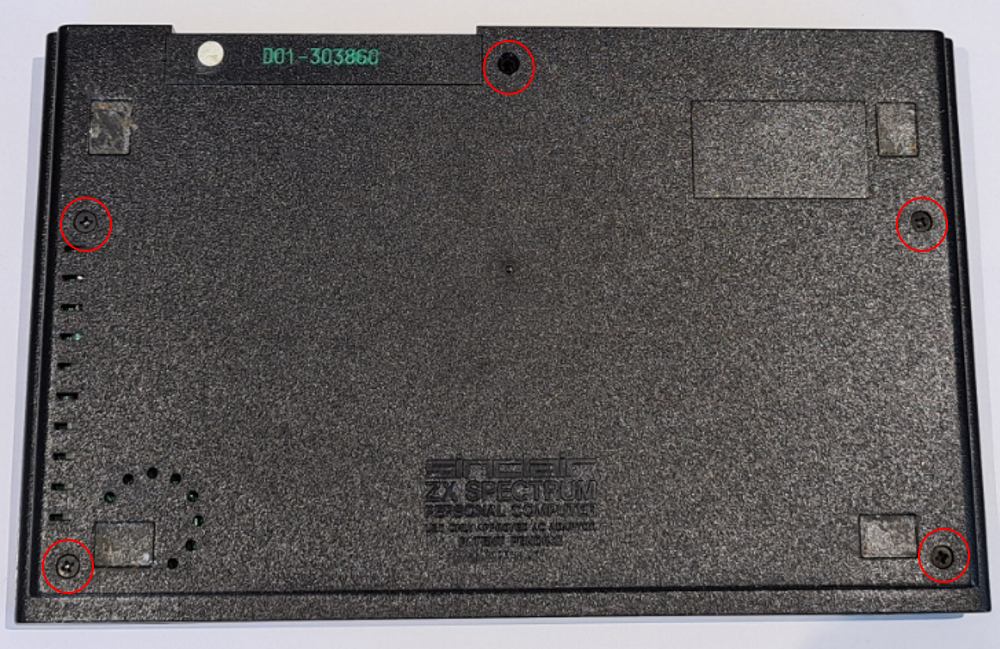
Open the ZX Spectrum by removing the screws on the underside of the computer. Put them aside someplace safe.
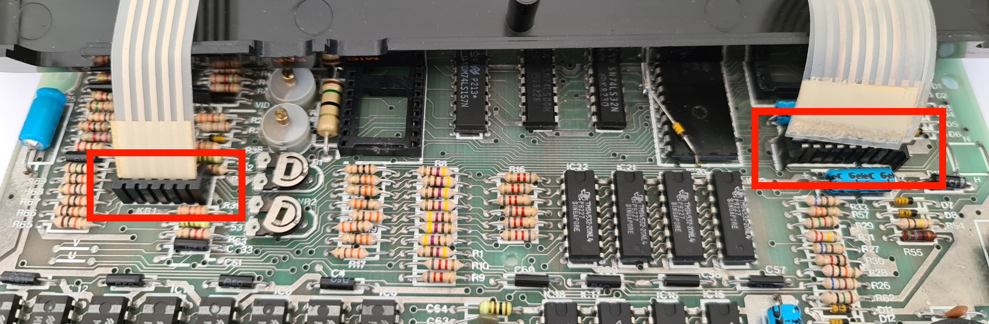
Once done, do not separate the halves of the case, but turn the computer the correct way up and place on your bench. Carefully lift the top part of the case and look underneath for the two flat ribbon cables that attach the keyboard to the computer. Pull these ribbon cables up very gently out of the sockets (be careful here that you don’t break the cables as they can be very brittle with age).
Once the two halves of the case are separated, you will see that the board is held into the bottom of the case by a screw. Remove this and put it to one side. Then remove the board from the bottom of the case.
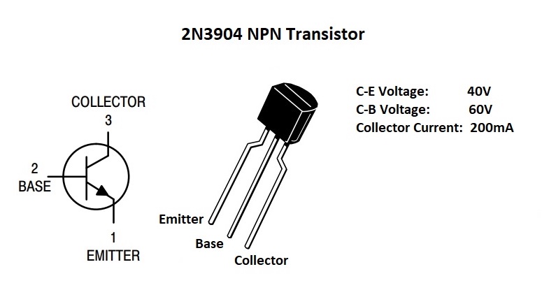
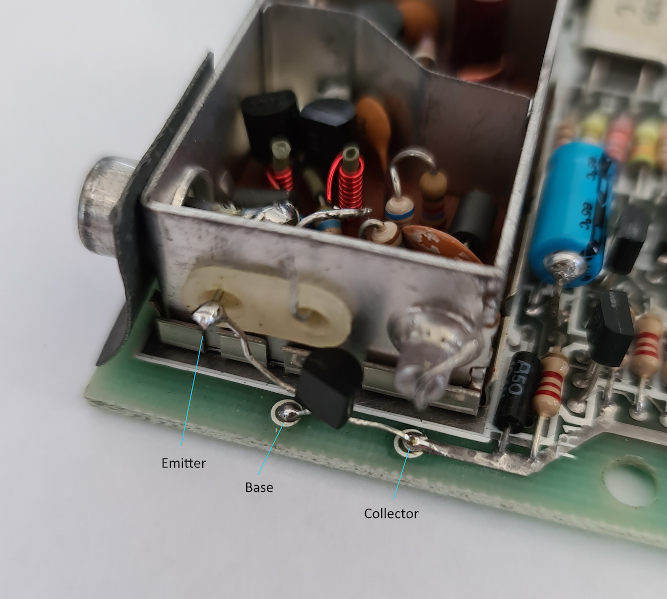
In the upper left-hand corner of the board you will see the silver square box which is the RF modulator. There are two wires that come out of the left-hand side of it. You will need to unsolder these wires from the board. Once unsoldered, just bend the two wires up so that they can be tucked away under the RF modulator cap when it is put back on. Doing this will allow us to make the modification reversable should we ever want to do that in the future. Make sure that the holes that these wires were soldered into are free of solder as you will be soldering the 2N3904 transistor into these.
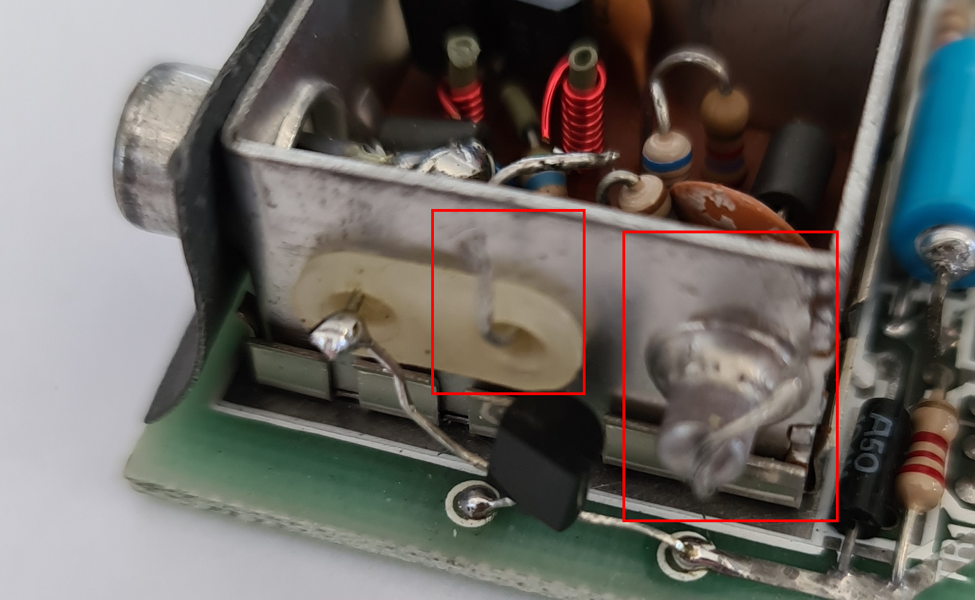
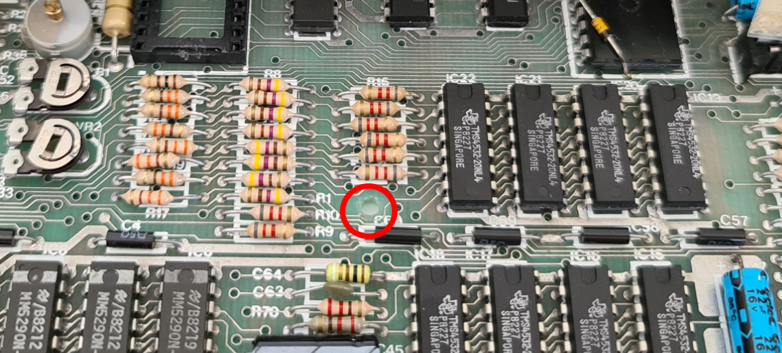
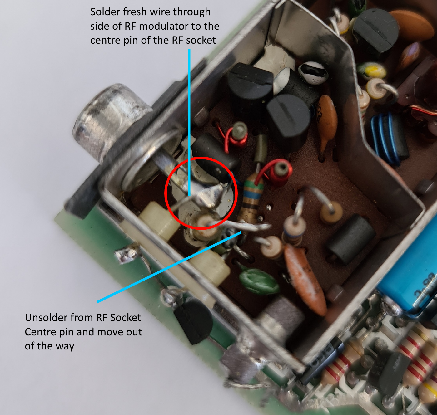
You will need to solder a bit of wire (a leg from an old resistor or capacitor) through the left-hand port and onto the middle pin of the RF socket. There is a resistor attached to that which you will have to remove first – see the picture.
If everything works fine, reassemble the Spectrum, remembering to put the screw back into the motherboard, close-up the case and replace the screws into the back to secure everything once again. Be very careful when putting the ribbon cables back into the keyboard connectors. They get very brittle with age. The best way I’ve found in doing this is to use two hands – pinch each ribbon cable at each side between your thumb and forefingers on each hand and gently push the ribbon into the connector with even pressure at both sides. Don’t try and just force them in. You should feel a bit of resistance and then feel the ribbon slide into the connector.
You can then test the output by connecting a phono lead (male to male) to the RF socket and into the composite video connection of your TV. Power up the ZX and you should see a nice picture.
Happy modding!